Construction Features of Pinch Roll & Wire Rod Laying Head

Construction Features of Pinch Roll & Wire Rod Laying Head
The pinch roll and wire rod laying head are closely adjacent semi-open system. The pinch roll is arranged before the entrance of the wire rod laying head and transportation of the gripping rolled piece into the wire rod laying head.
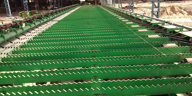
Then wire discharger will transform the gripping rolled piece to helici form rolled piece which a diameter is 1080mm and flat the rolled out to the scattered coils cooling roll table.
Pinch Roll
It is the horizontal cantilever structure. It has a double roll device and one air cylinder which is used to control the roll up and down synchronous clamp. The Pinch roll DC motor is used to improve drive speed by two-stage cylindrical gear. Up and down rolls are installed respectively at two swing arms. There is one air cylinder that drives the up and down roll synchronously close to or leaves the rolling line by a group of crank-link mechanisms.
There is equipped with adjustable limit equipment to adjust the pinch roll max opening degree and minimum center distance between the up and down roll so that could adjust the clamping force and wire rod not too fast simultaneously. Pinch roll drive gearbox used welding structure.
The gear and bearings used a thin oil central lubrication process. And the bearings are used filmatic bearings and high-speed roll thrust bearings. Pinch roll is long-running at regular work and its speed is set by process requirements. Pinch roll can clamp the head, end, or whole wire rod on the basis of process requirement.
Wire Rod Laying Head
It is the vertical cantilever structure and the center line slopes down ten degrees. It consists of a spinning pipe that is installed in the rotation dabber and gearing. There is one DC adjustable-speed motor that could drive the rotation dabber through a pair of bevel-gear wheels. The spinning pipe can spin a regular wire coil on the basis of setting revolving speed.
Wire rod laying head rotation dabber consists of the spinning head and hollow shaft. The spinning head is used to fixation the spinning pipe and hollow shaft. And the hollow shaft would be driven by a bevel gear in the driving box.
There is a pipe among the internal bevel gear. And there is a water-cooling drivepipe between the pipe and the hollow shaft. Water-cooling drivepipe is used for cooling the pipe and it will protect the bearings of the hollow shaft to keep it away from the high temperature of rolled piece.
Wire rod laying head drive gearbox used welding structure. The gear and bearings used a thin oil central lubrication process.
The safety guard is the cylinder structure and the spinning head is installed in it. Its incline design is for security.
The top half of the safety guard can be opened by the air cylinder for changing the spinning pipe but it must be closed at regular work. It should be processed static balancing test for all of the equipment with rotation dabber.
Then we can increase or decrease their weight of them on basis of testing.
After the static balancing test, it should be processed dynamic balance test which measures datum: testing rotation speed: 1900r/min, dynamic balance quality: G2.5. There are two test points in the front and back bearing cap when the wire discharger is assembled you could test vibration data on the two points. And the test vibration measure data is 5mm/s.


评论
发表评论